What Are the Main Parts of a Tower Crane?
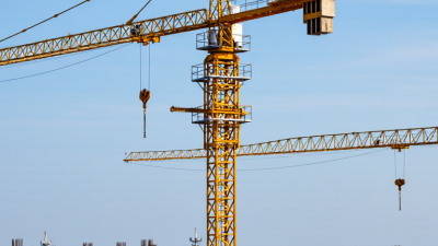
A tower crane is easy to recognize on a busy construction site: a tall mast supports a long horizontal jib, while a hook moves loads above the work area. Yet its appearance tells only part of the story. The Parts Of Tower Crane work together to lift, slew, travel, and hold loads in controlled ways. Small differences between models matter.
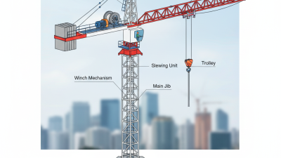
The mast forms the tower’s vertical structure, and its base transfers forces into a designed foundation. At the top, the slewing unit turns the crane. The jib carries the trolley and hook, while the shorter counter-jib supports machinery and counterweights. A hoist raises or lowers the load; the trolley moves it along the jib. The operator’s cab, motors, brakes, and control systems support that movement. Some cranes also use climbing frames or building ties as the structure rises.
A diagram makes these components look tidy. A real site is less tidy: wind, changing loads, nearby structures, and installation conditions all affect crane operation. That detail deserves attention. This outline introduces the main parts and explains what each contributes, without treating every tower crane as identical. Component layouts vary by design, capacity, and setup. For practical decisions, site teams should rely on the manufacturer’s documentation and inspection by qualified personnel. The hook may draw the eye, but safe lifting depends on the complete system—and on people checking how its parts work together.

Tower Crane Layout: Mast Sections Commonly Measure 3–6 m
A tower crane’s mast is built from bolted steel sections, commonly 3–6 m high, according to published crane configuration schedules and erection documentation. The range is a practical industry benchmark, not a universal rule. EN 14439, the European safety standard for tower cranes, sets safety requirements but does not prescribe one mast-section height. ISO 4306-3:2016 defines tower-crane terminology, helping teams describe components consistently.
Section height affects more than the crane’s overall reach. A 3 m module allows finer adjustment around a tight site, while a 6 m module can reduce the number of joints and lifting cycles. Every joint still needs correct alignment and bolt tightening. Small errors matter. Before assembly, site teams check the section type, connection points, and lifting plan against the crane’s approved configuration. This is where assumptions can slip: two sections with similar dimensions may not be interchangeable. Actual sizes vary with crane design, load requirements, and local conditions, so project drawings and the erection manual should take precedence over the 3–6 m rule of thumb.
What Are the Main Parts of a Tower Crane? - Tower Crane Layout: Mast Sections Commonly Measure 3–6 m
| Crane Part |
Typical Layout or Dimension |
Main Function |
| Foundation or base |
A ground-supported concrete foundation or an engineered base frame; design depends on soil conditions and crane loads. |
Transfers the crane’s forces safely into the ground or supporting structure. |
| Mast sections |
Modular lattice-steel sections commonly measure about 3–6 m in height; exact dimensions and connections vary by crane design. |
Forms the vertical tower and supports the slewing assembly and working parts of the crane. |
| Tower head or slewing assembly |
Mounted at the top of the mast; includes the slew ring and drive equipment. |
Allows the upper structure to rotate horizontally around the mast. |
| Jib (working arm) |
Projects outward from the tower; length is crane-specific and may be configured in sections. |
Provides the working radius along which loads can be moved. |
| Counter-jib |
Extends behind the tower head, opposite the working jib. |
Supports the counterweights and commonly carries hoisting machinery. |
| Counterweights |
Placed on the counter-jib in a specified arrangement and amount for the crane configuration. |
Balances the working jib and helps maintain stability within the rated operating limits. |
| Trolley |
Travels along the jib on a horizontal track or rail system. |
Moves the suspended load toward or away from the tower to change its working radius. |
| Hoist, wire rope, and hook block |
The hoist is typically mounted on the counter-jib; the rope runs through the crane’s reeving system to the hook block. |
Raises and lowers loads; the hook block provides the load connection. |
| Operator’s cab and controls |
Usually positioned near the slewing assembly, with visibility and access dependent on crane layout. |
Houses the operator station and controls used to operate crane movements. |
| Tie-ins and climbing frame (when required) |
Tie-ins connect the mast to a building or structure; a climbing frame may be used to add mast sections as the crane rises. |
Provides lateral support or enables tower height to be increased, according to the engineered erection plan. |
Note: Dimensions and component arrangements vary by crane design, capacity, site conditions, and installation configuration. Always follow the crane manufacturer’s technical documentation and the approved lift and erection plans.
Mast, Slewing Unit, and Cab: Enabling 360° Crane Rotation
A tower crane’s mast is its tall, braced backbone. Made from connected steel sections, it carries the crane’s load down to the foundation. Each joint must be assembled and checked carefully; small alignment errors can matter as the structure grows. The mast itself stays fixed during normal slewing. The upper crane turns above it.
That movement happens at the slewing unit, which includes a large bearing and drive system near the mast top. The bearing supports the rotating upperworks, while motors and gears turn the jib, counter-jib, and cab around the mast. One full turn gives the crane 360-degree access. Slowly, but with great force. Rotation is controlled, not a free spin, and wind or load conditions affect how the crane is operated.
The cab sits on the rotating upper structure, giving the operator a view that changes as the crane swings. Controls, gauges, and radio communication help coordinate movement with workers on the ground. Yet the cab cannot provide a clear view of every point. Blind areas remain, especially behind the load or structure, so trained operators rely on signals and agreed procedures. A drawing makes the arrangement look simple; on site, visibility and timing are less tidy than the diagram suggests.
What Are the Main Parts of a Tower Crane?
Mast, Slewing Unit, and Cab: Enabling 360° Crane Rotation
The chart illustrates the slewing unit turning through one complete revolution. The mast supports the crane structure, while the cab houses the operator’s controls. Values show angular position, not a measured operating speed.
Jib and Counterjib: Balancing Loads Across Jibs Up to About 80 m
A tower crane’s jib reaches over the work area, while its counterjib projects behind the mast. Together, they balance lifting forces around the tower’s central axis. A jib may extend to about 80 m, but that figure is not a universal safe reach or a measure of lifting capacity. The CICA Tower Crane Code of Practice emphasizes using the crane’s configuration-specific load chart when planning lifts.
The counterjib carries counterweights and often machinery, creating a balancing moment opposite the load. The key is distance from the mast, not simply equal weights on both sides. As the trolley moves outward, the load’s leverage increases, and the crane’s permitted capacity generally falls. Near the jib tip, even a modest load can exceed the chart limit. Wind and the crane’s setup also matter. The load chart is the authority; visual judgment is not enough.
Tips: Before lifting, confirm the jib length, trolley radius, counterweight arrangement, and exact load against the chart. Check the site wind readings too. A pallet that looks small can still be heavy. And, honestly, rushed checks remain an uncomfortable weakness on busy sites.
Hoist, Trolley, and Hook: Tip Capacity Often Falls to 1–2 Tonnes
A tower crane’s hoist raises the load, while the trolley moves it along the jib. The hook connects the lifting gear to the load. At the jib tip, capacity often falls to about 1–2 tonnes, but this is not a universal rating. The exact limit depends on the crane’s configuration and its rated-load chart.
The reason is leverage. As the trolley travels outward, the load acts farther from the mast, increasing the overturning moment. A concrete skip that is acceptable near the tower may exceed the chart limit at the tip. OSHA’s construction-crane rule, 29 CFR 1926.1417, requires operators to follow applicable rated-capacity information and account for load weight. Check the chart for the actual jib length, radius, and operating setup. Small details matter.
The hook’s weight and lifting gear also use part of the available capacity. So do slings and other attachments, depending on how the chart defines the rated load. On site, a load may look manageable and still be too heavy at full reach. That judgment can be wrong. Wind limits and crane configuration require separate checks; a simple “one-to-two-tonne tip” rule cannot replace the chart.
Base, Anchors, and Ties: Supporting Free-Standing Heights Near 80 m
What Are the Main Parts of a Tower Crane?
Base, Anchors, and Ties: Supporting Free-Standing Heights Near 80 m
A tower crane’s height depends on more than its mast sections. The base transfers the crane’s weight and working forces into the ground. On site, this may mean a reinforced concrete foundation with anchor bolts set precisely in place. Small errors matter. A level check and careful review of the foundation drawings help catch problems before the mast rises.
Near 80 m, “free-standing” needs context. Some cranes can reach heights around this range without building ties, but the permitted height depends on the crane configuration, wind conditions, and ground support. Anchors resist uplift and overturning forces; they are not a substitute for a properly designed foundation. When a crane grows beyond its approved free-standing height, tie frames connect the mast to the building at specified levels. They transfer horizontal loads into the structure. The details are easy to underestimate. Tie locations, connections, and inspection access all deserve attention, and the building must be able to carry those loads. A rushed assumption about height can create an expensive—and avoidable—problem.